WELCOME TO TELEGRAPHKEYS.COM
**NEW**
6/1/2026:
--Created a new page for Amateur Radio Keys
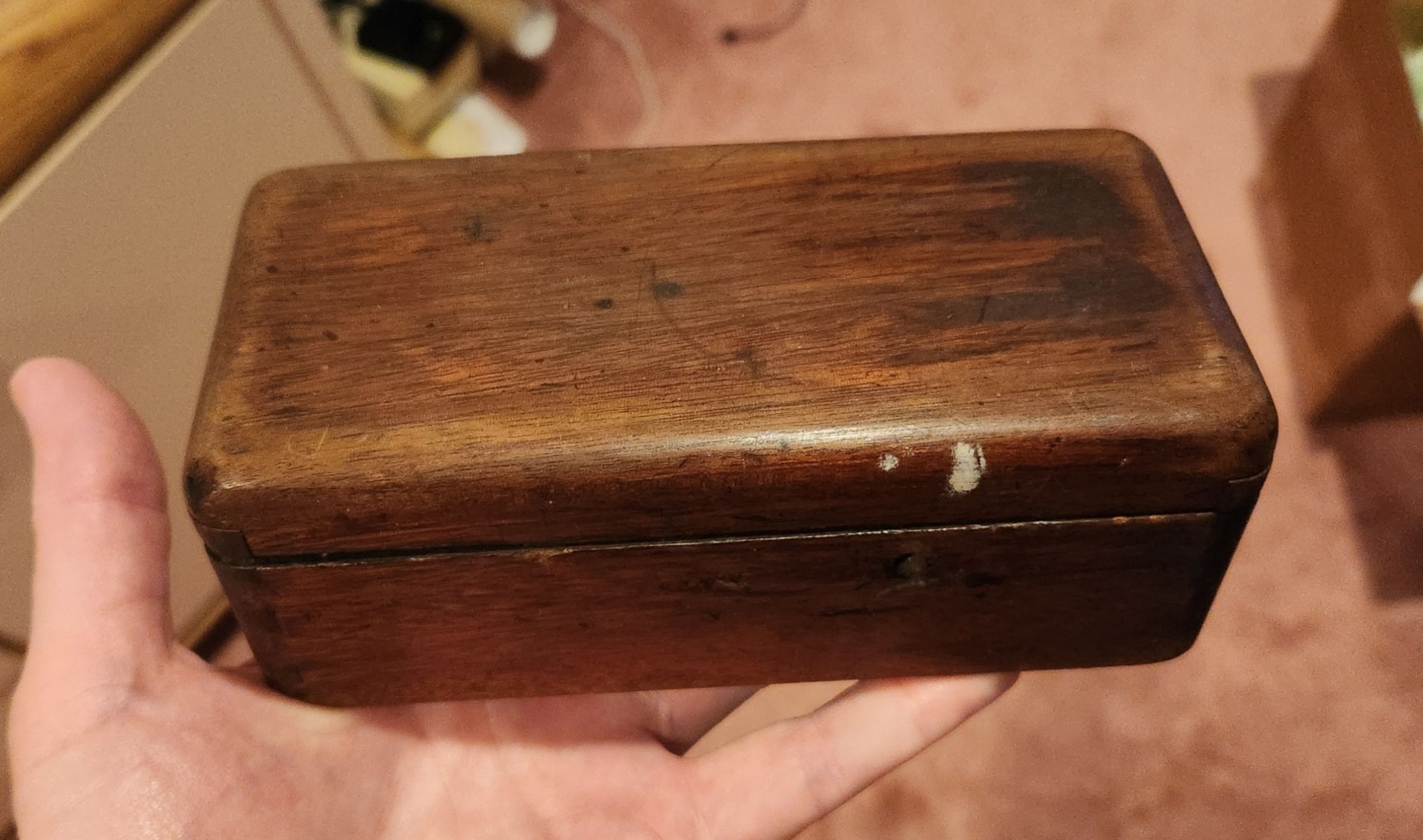
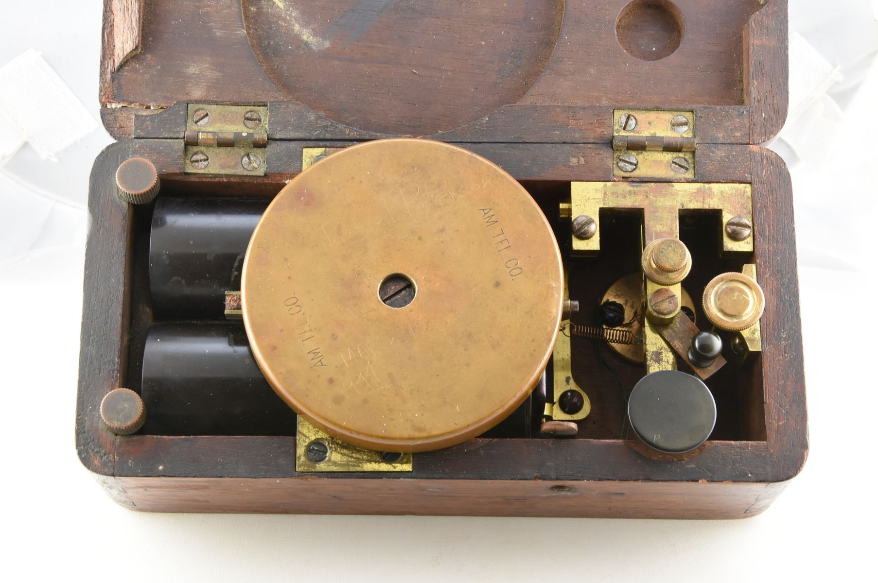
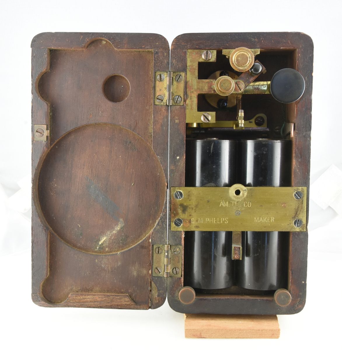
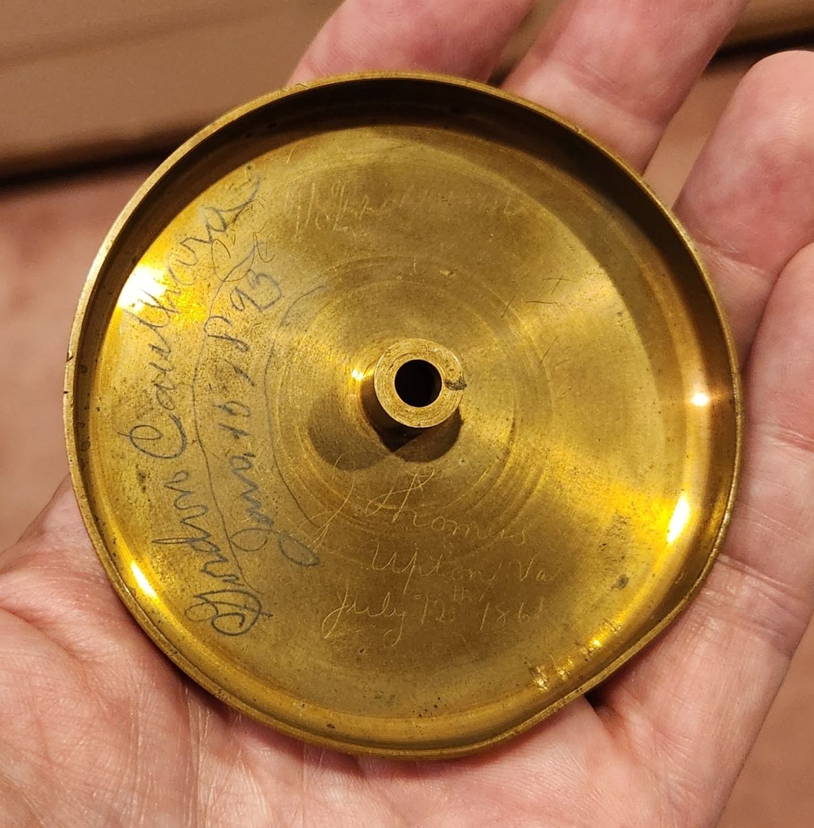
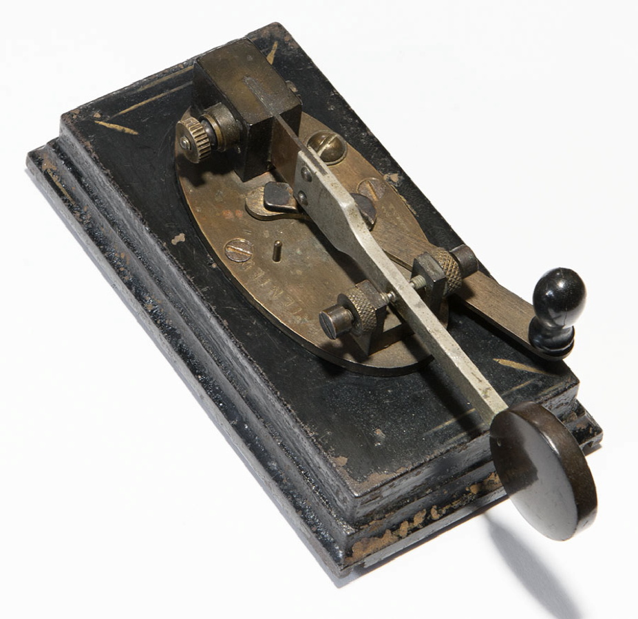
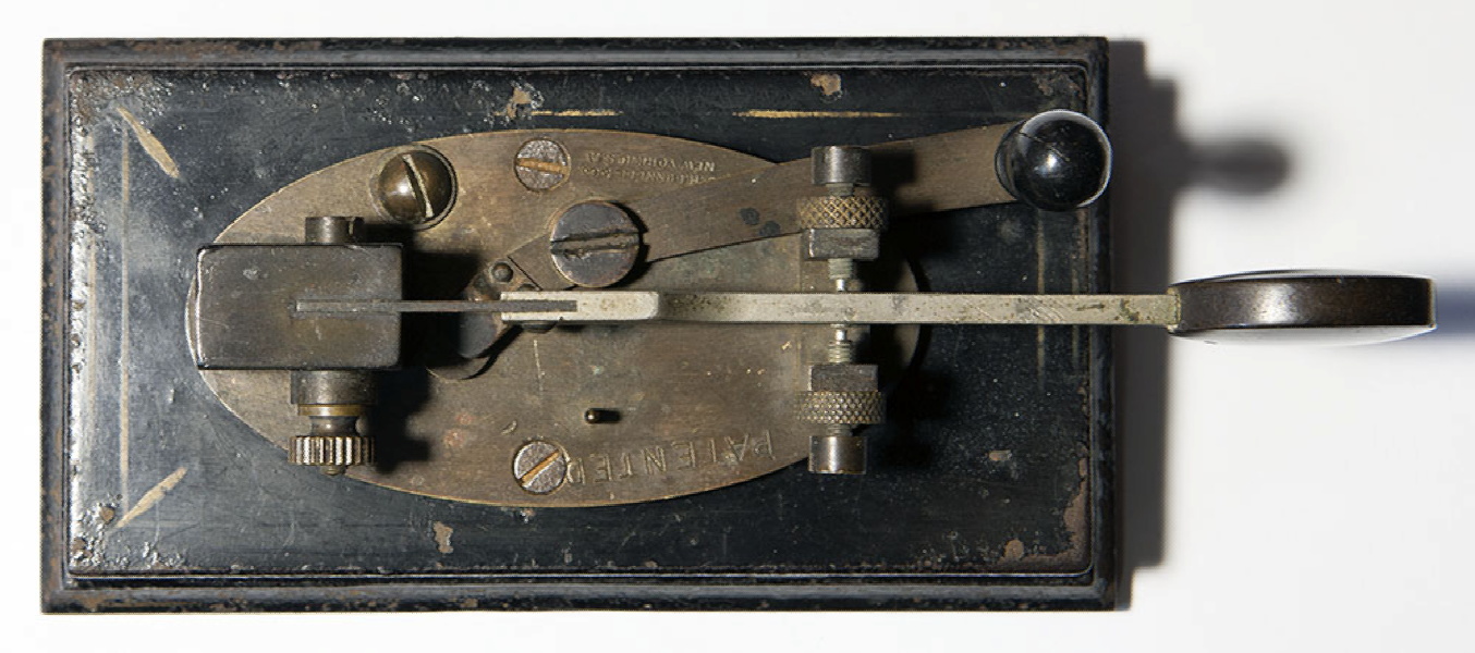
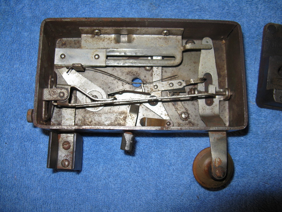
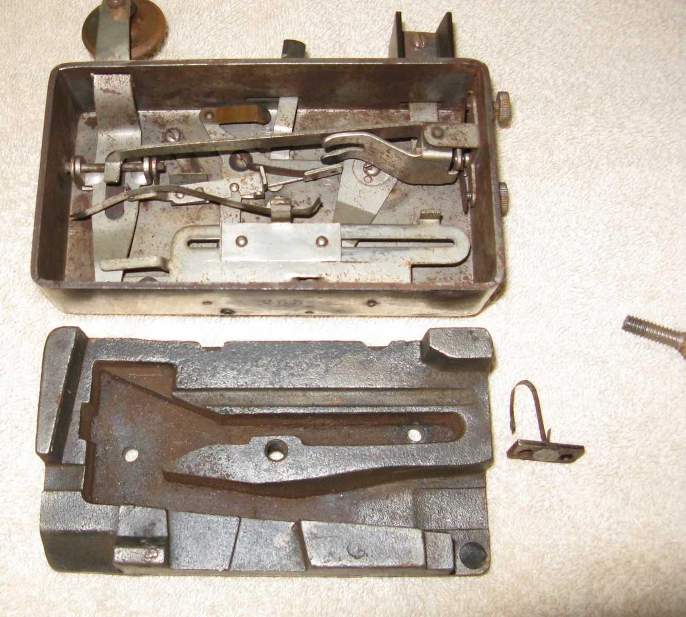
--Added pictures of a Civil War field telegraph set, made by GM Phelps, NY. (Pic 1, Pic 2, Pic 3, Pic 4)
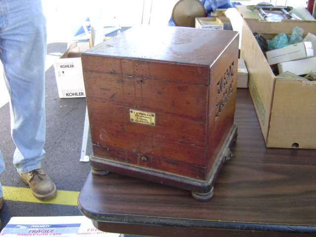
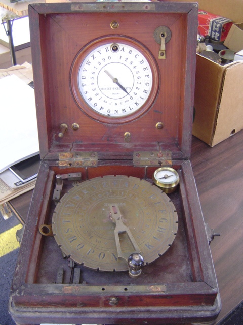
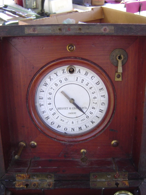
--Added pictures of an early Dial Telegraph set by Breguet & Crossley, Great Britain. (Pic 1, Pic 2, Pic 3)
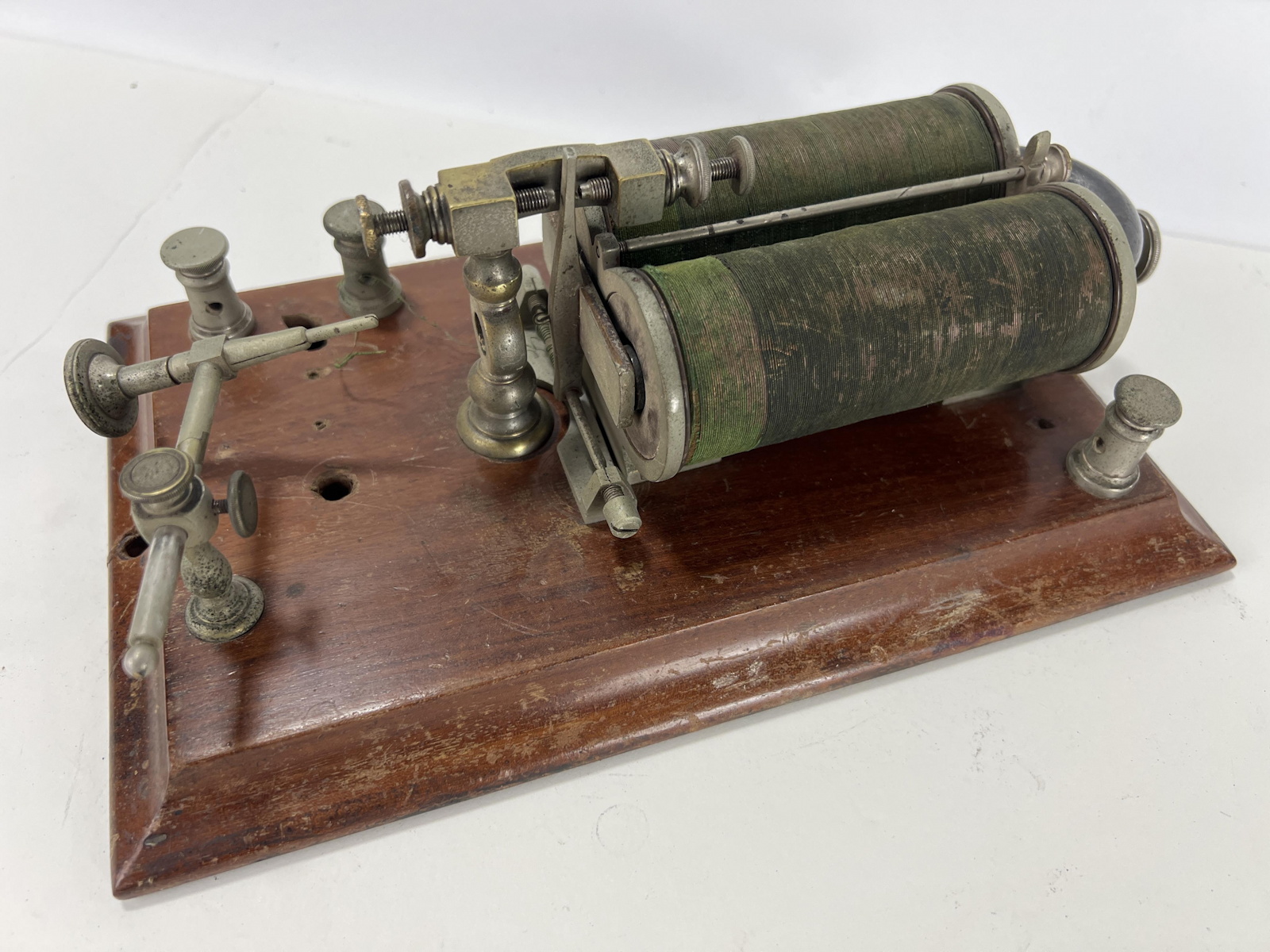
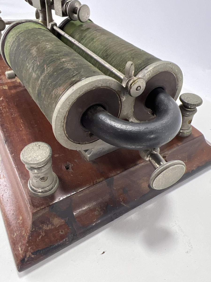
--Added pictures of a large nickel plated relay by Charles T. Chester, NY. (Pic 1, Pic 2)
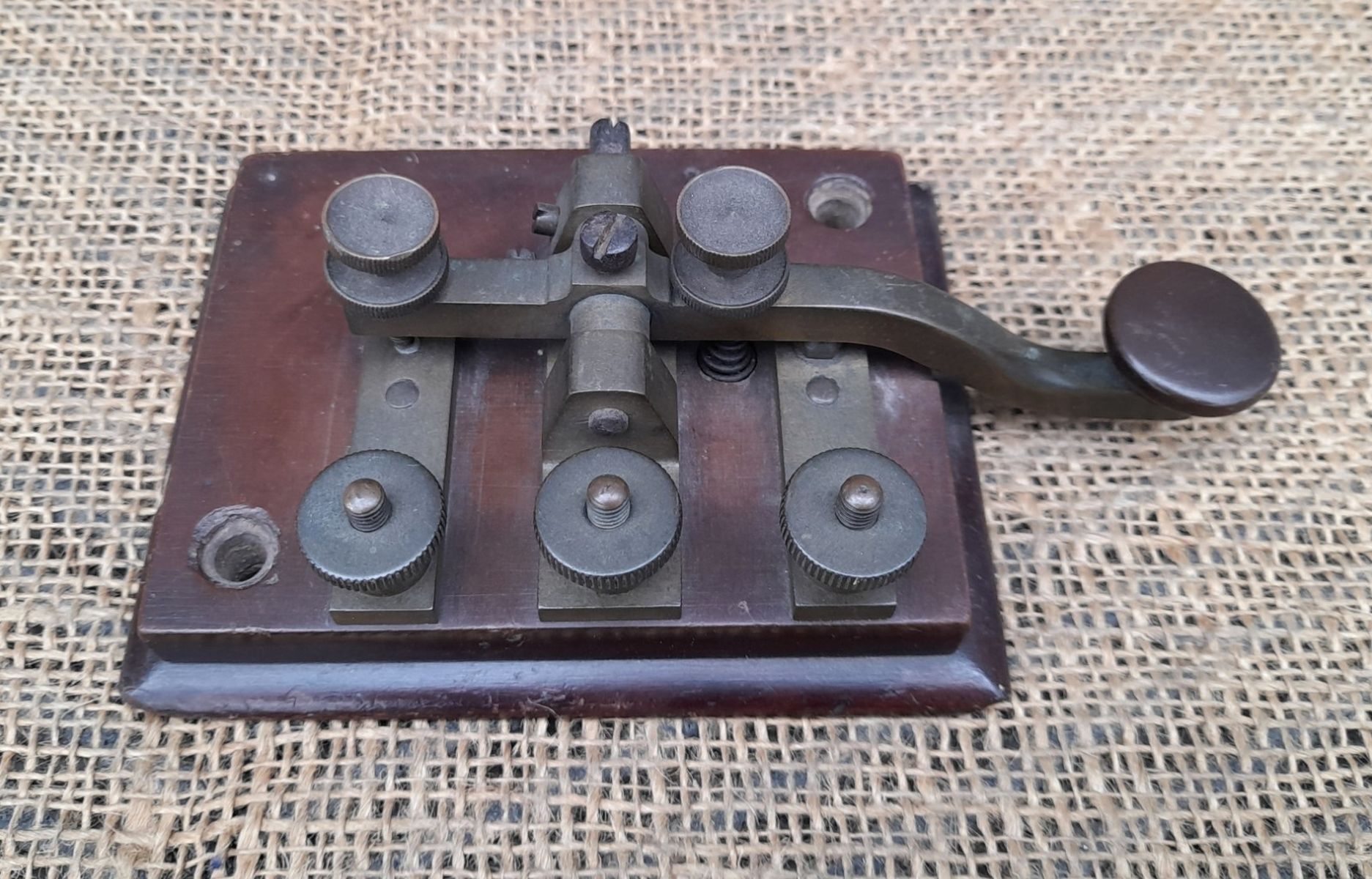
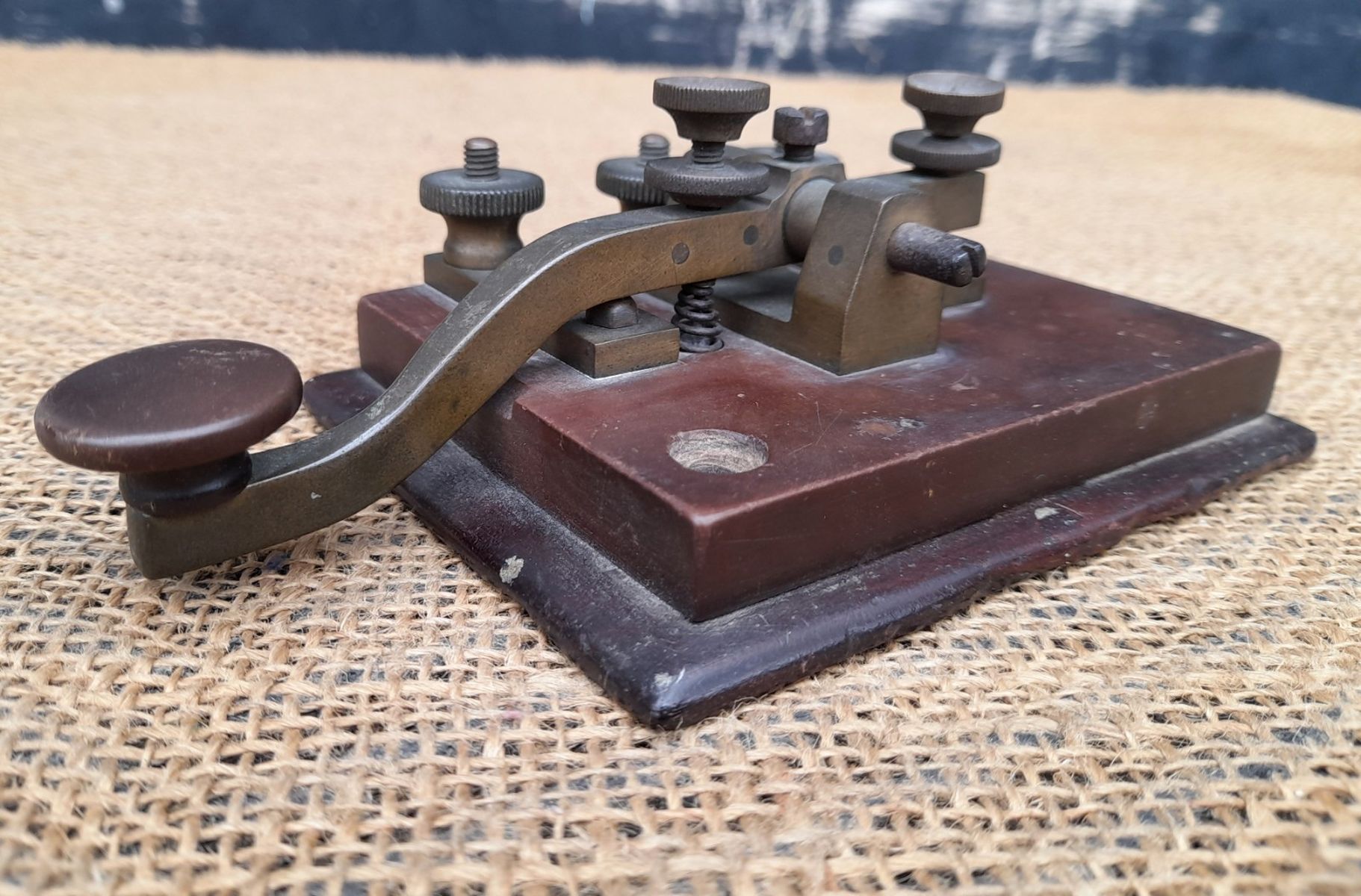
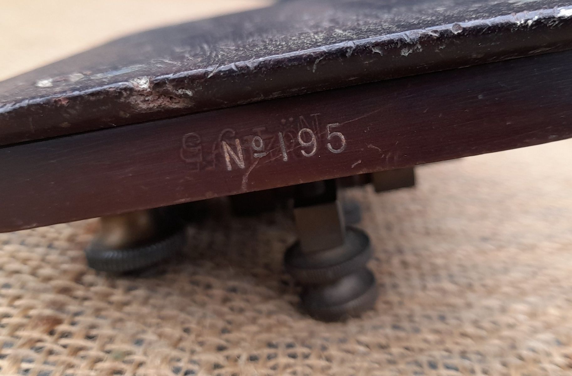
--Added pictures of an early Indian postal key, maker unknown. (Pic 1, Pic 2, Pic 3)
--Added pictures of a rare Bunnell Type "G" Sideswiper Key (Gerry Maira, KA2MGE collection). (Pic 1, Pic 2)
--Added pictures of the Mecograph Model 2 (Combo Model). (Pic 1, Pic 2, Pic 3)
--Added pictures of The Conkling Key, a rare bug that produces automatic dots. (Pic 1, Pic 2, Pic 3, Pic 4)
--Added pictures of the rare Brown Brothers Model ES single lever paddle. (Pic 1, Pic 2)
I created this website to provide a comprehensive timeline of telegraph instruments in photographs. Pictures of telegraph instruments can be found all over the web; however, they tend to be scattered amongst on-line auction sites, as well as collectors' and museum websites. So, what I am attempting to do with telegraphkeys.com is to compile a collection of photographs from multiple sources, many from my own collection, in order to present a more complete picture of the history of telegraph instruments. Although the site focuses mainly on photo galleries, I will be adding more information to the website as time allows, concerning other topics such as telegraph key restoration methods, telegraph patents, tips on collecting, etc. Check back from time to time to see any new information that's been added.
For those of you that are primarily interested in the history of telegraph, there are some outstanding websites that are focused on the historical aspects of the telegraph. So rather than trying to re-invent the wheel, I defer to these historians to provide the information you seek. Please check out my LINKS page to visit these particular websites.
How to Use This Website
The buttons on the left link to photo galleries of the different types of telegraph instruments, such as straight keys, sounders, bugs, registers, etc. Click on one of the buttons to see pictures of these instruments organized approximately by age. See below for a description of the different types of apparatus:
Straight Keys
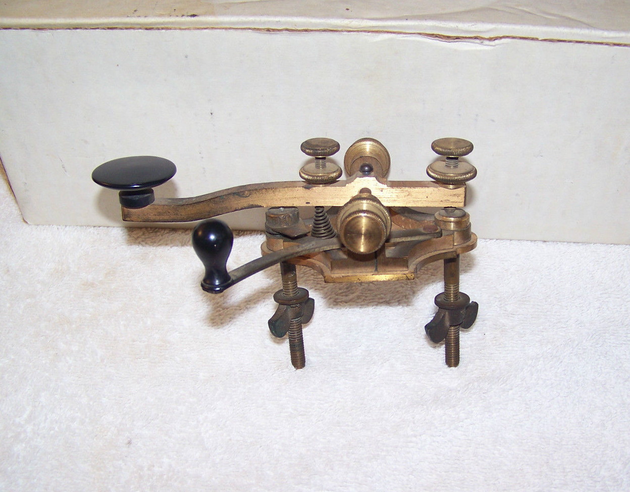 Also known as the Hand Key, this was the basic tool for sending Morse Code. The key is basically a simple on-off switch with a lever that pivots over a base. An insulated contact is located at the front of the base. Older keys used on landline circuits also have a circuit closer, which was used to close the circuit when the operator was listening to traffic on the line. When he wanted to send a message, the switch was opened.
In addition to landline keys, there were also wireless or spark keys. These were used with the first radio systems and typically had much larger contacts than landline keys in order to handle the high currents of the early wireless systems.
There were also keys used for undersea cable telegraph communication, light-signaling keys, radio keys, mechanical practice keys, and keyer paddles used with electronic keyers.
Registers
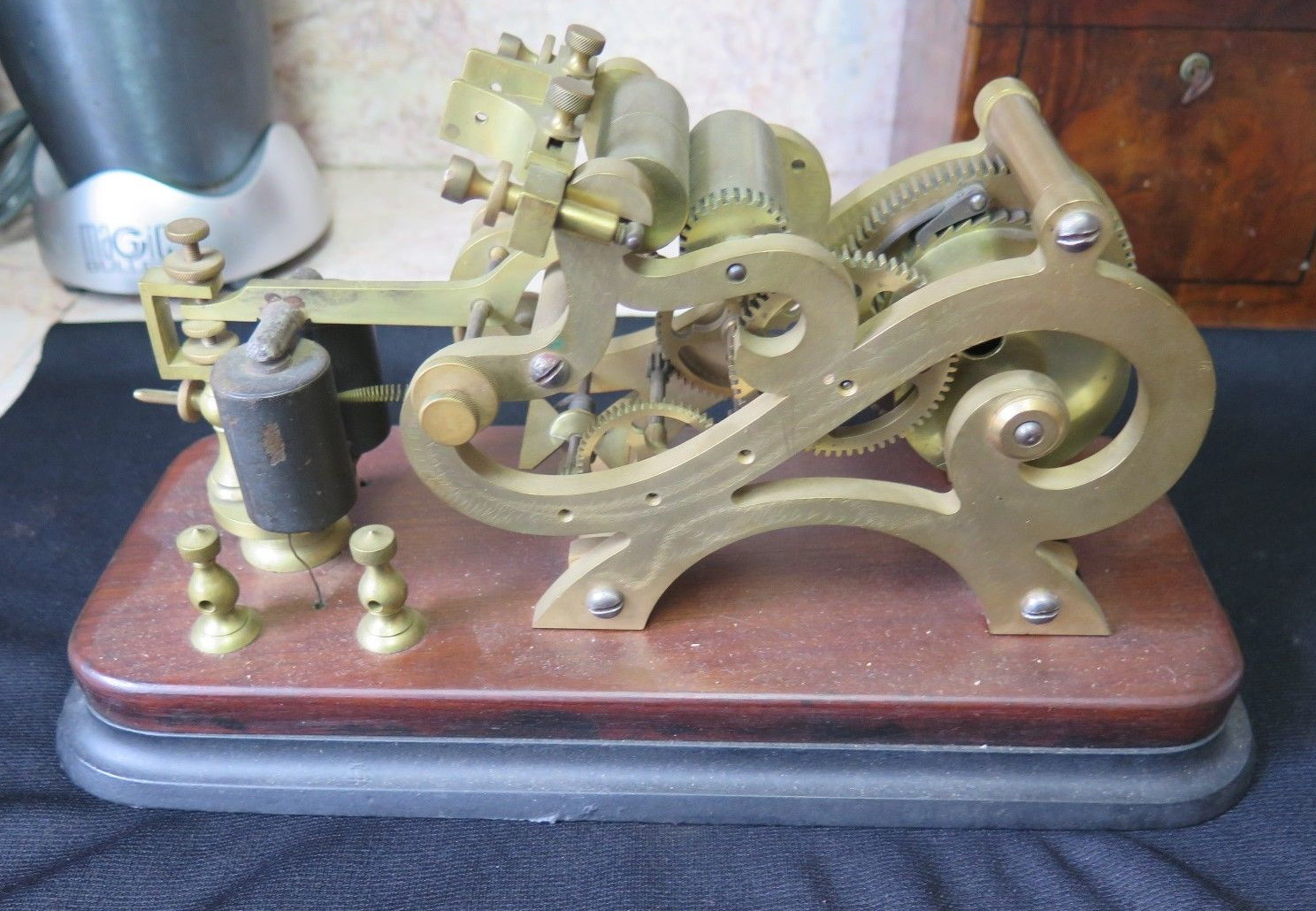 The Register is the earliest form of telegraph receiver. The register is a fairly large instrument, consisting of a clockwork mechanism that pulls a paper tape though the instrument. Also there is pair of electromagnets which is energized by an incoming telegraph signal. The magnetic field produced by the electromagnets pulls down on a lever, at the other end of which is a metal stylus. When properly adjusted, this stylus will create a “dent” in the paper tape to record the telegraph signal. This process is known as “embossing”. The earlier registers, up until the 1870’s, used a large weight on a rope to run the clockwork mechanism, much like a grandfather clock; hence were knows as weight driven registers. Later designs replaced the weight and rope with a wind-up spring. By 1880 the register was hardly being used in the U.S. but continued to be used in Europe well into the 20th Century.
Sounders & Relays
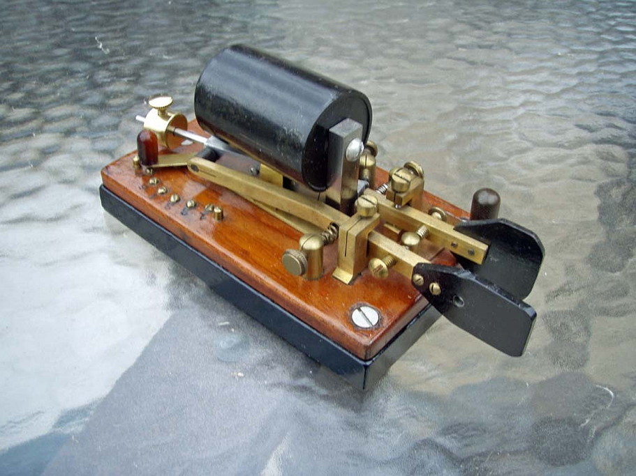
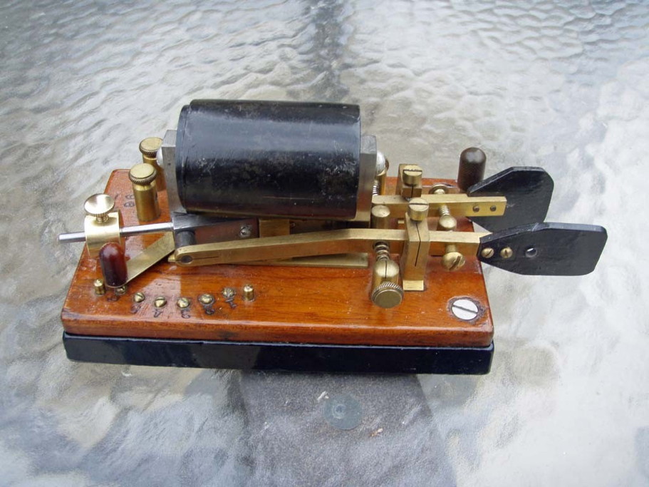
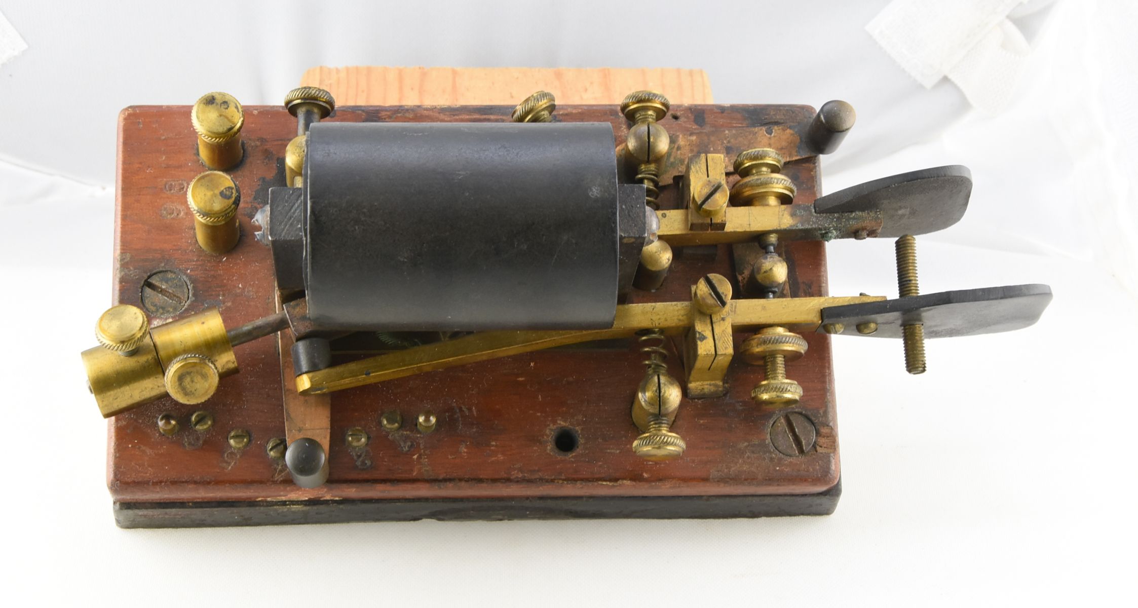
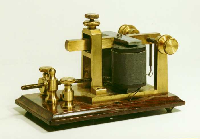 After telegraph communications became more commonplace, many operators learned to read the incoming signal just by listening to the weak clicking sound produced by the register. Soon after this, sometime in the late 1850’s, the sounder was invented. A sounder is an electromagnetic device just like a register and was designed, as the name suggests, to amplify the sound of the lever clicking. The signal passes through an electromagnet, pulling down a lever which hits against an “anvil” and makes a loud clicking noise, much louder than the sound produced by a register. Various neat sounder designs were made over the years, some with very ornate machining. Even after the invention of the sounder, the register was still widely used, especially by the railroads, in order to maintain a record of the communications in the event of an accident.
A relay operates basically the same way as a sounder, but is designed for switching between two or more circuits. It uses the same electromagnet as a sounder but does not produce a very loud clicking noise. You can distinguish a relay from a sounder by the fact that it has more than one pair of binding posts for wire attachment. Also, relays generally have larger electromagnets (more turns of wire, thus higher resistance) which makes them more sensitive to weak currents on the main telegraph line.
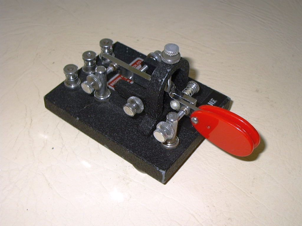
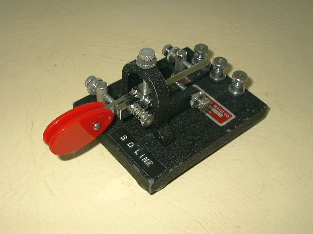
Bugs (Semi-Automatic Keys)
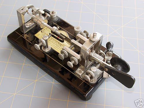 The Semi-Automatic Key, also known as the Bug Key (or simply Bug), was invented by Horace Martin in 1902 (The Vibroplex Company) in order to cure the problem of “Glass Arm” (known today as Carpal Tunnel Syndrome). Telegraph operators of the 19th Century would frequently suffer from paralysis due to the constant up & down motion of operating a telegraph key all day. With the Bug Key, the lever moves from side to side, producing dots in one direction and dashes in the other. The dash side operated much like a regular straight key turned on its side, but the dots were created by a vibrating pendulum which essentially allowed the operator to send a series of dots automatically without having to exercise multiple wrist motions, thus greatly reducing the problem of Glass Arm. The invention of the Bug Key revolutionized telegraphy, and many companies tried to copy Horace Martin’s design, resulting in numerous court battles. However, other companies did come up with all sorts of neat modifications and design changes to make their keys unique. Some of these "oddball" bugs are highly collectable.
Pocket Sets
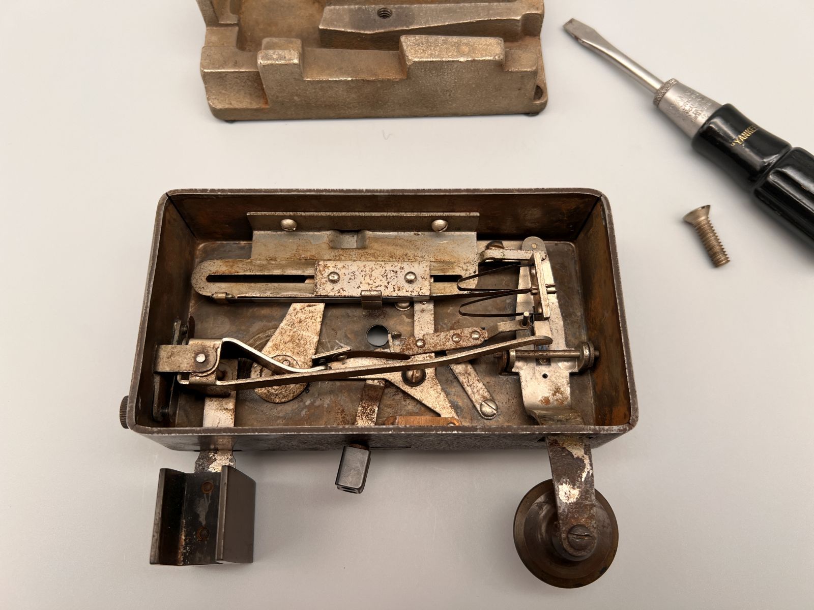
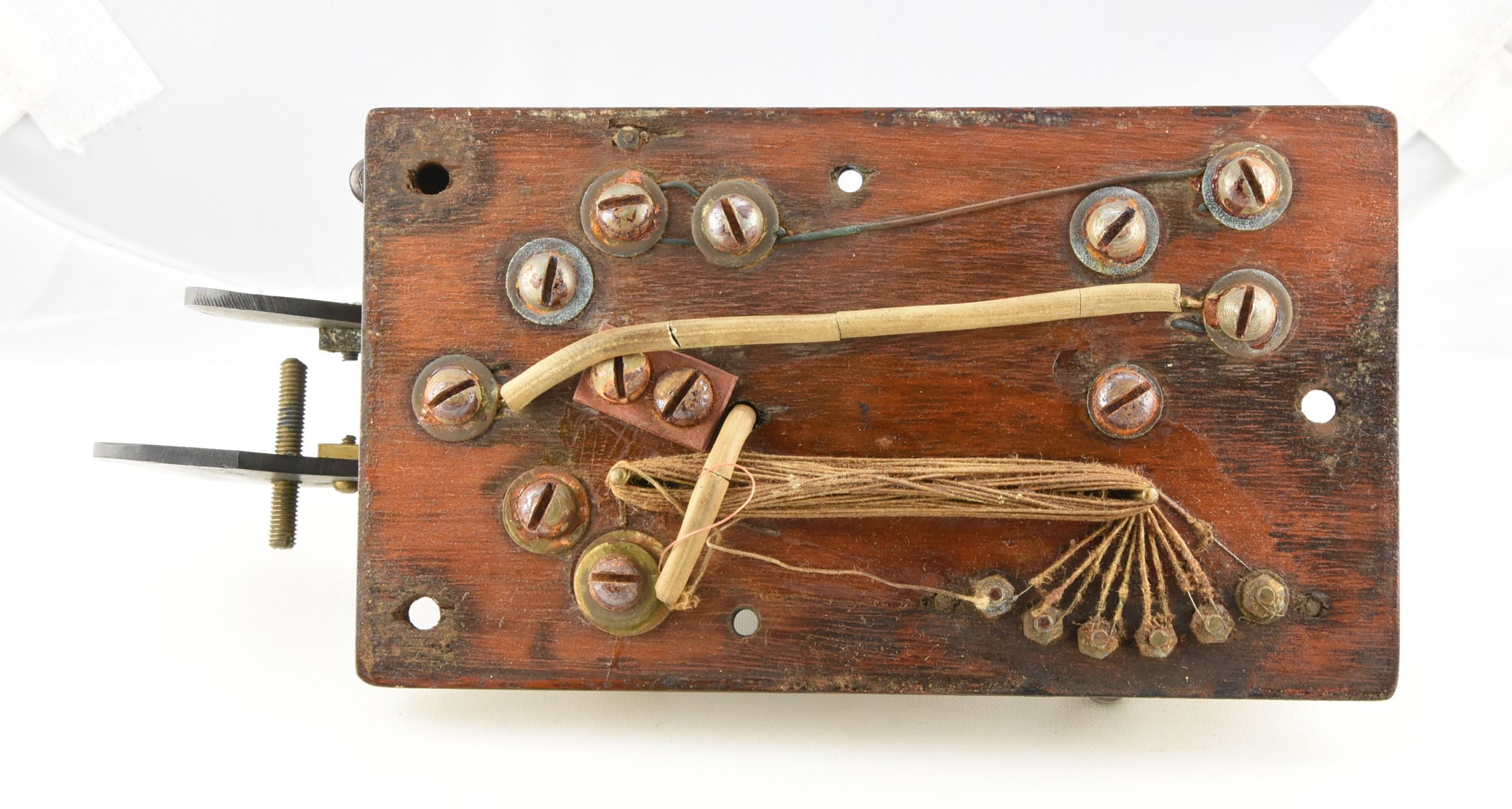
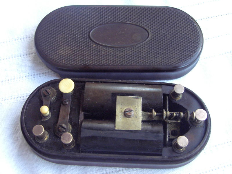 A Pocket Set, or a Pocket Relay, is a small self-contained telegraph set consisting of a tiny key and relay in a case small enough to fit in an operator’s pocket. They were designed to be used by telegraph line workers who had to work out in the field to diagnose issues with the lines. The line worker would use the small instrument to tap into the line for troubleshooting. Many interesting varieties of these sets are known to exist. Some are actually too big to fit into a pocket but the operating principle is the same. (I refer to these as "small boxed sets" but include them in the same category as pocket sets).
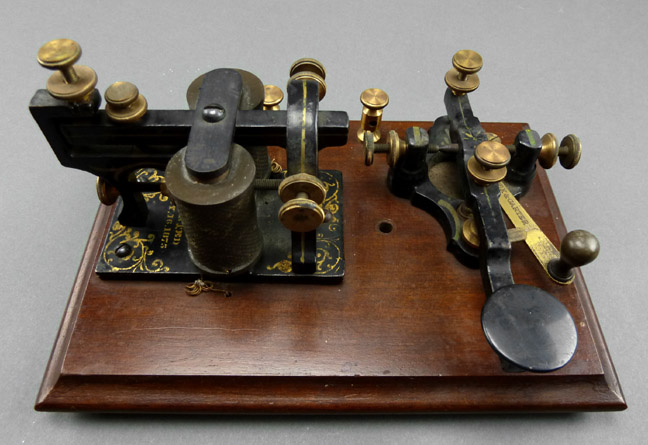 KOB stands for “Key on Board”. It consists of a straight key and a sounder mounted on a single wooden or metal base. They could be used as a simple set for practicing Morse Code, or actually used in a telegraph office. During the Victorian Era, KOB sets were sometimes used in large homes in order to communicate between different rooms. These were referred to as Private Line Sets, which were analogous to an intercom system you might find in a modern home.
In England they often mounted a key, sounder and galvanometer on a single base. These were called Baseboard Sets. In continental Europe it was common to mount a key, register and sometimes a galvanometer together on a base. Some refer to this type of set as a KROB, or Key and Register On Board.
Electronic Keyers & Keyer Paddles

Around 1939, the first electronic keyer was invented. It used vacuum tube circuitry to create a switching mechanism that produced automatic dots and dashes. It also included an audio oscillator so that the operator could now hear the Morse Code he was sending as an audio tone.
The early electronic keyer designs were fairly large devices, and had the keyer paddle built into the unit. As keyers became more popular, many companies began making stand-alone paddles and keyers. Hence, people could now use a variety of paddles with their electronic keyer. Also, with the invention of the transistor which replaced vacuum tubes, electronic keyers now took up much less room on the operator's desk.
Questions or comments?
You can reach me at telegraphdude@comcast.net
Number of Visitors Since April 27, 2016 (Samuel FB Morse's Birthday!):